
I was asked on how to configure LACP for AP’s connected to a controller and I was not able to answer this question out of my mind so I decided to figure it out for myself. And as always, when I need to test something, I write a post about it. This is my post on how to configure LACP for AP’s. I will describe this feature for controller-based AP’s and also for Instant AP’s
Connecting two ethernet ports has two main benefits:
- more bandwidth
- high availability for AP’s which can draw power on both ports
LACP for AP’s with Controller
If you use LACP for AP’s with a controller there are several flavors, depending on the controller setup you have. I will only show the most common ones, for a standalone controller and for a cluster of controllers, as I assume, that if you run more than one controller it will be a cluster.
LACP for AP’s with a Controller Cluster
This setup is the easiest one so it comes first. I assume, that you have
The first problem with LACP on an AP is that there is mostly only one type of communication, coming from the AP going to the Controller and vice versa. Only two types of protocols are involved, IPSec and GRE. IPSec does not matter, as this is only used for AP Controller communication. The important part is the GRE protocol as the client data is transferred in this GRE tunnel.
As there are only two communication partners involved the normal load sharing algorithms did not work. Most of the time it is L2 based. So we need to change this to L3 based load balancing.
For Comware based devices it looks like this:
link-aggregation global load-sharing mode destination-ip source-ipFor Aruba OS based switches this looks like this:
trunk-load-balance l3As we are running a cluster, each client will be connected to a different Controller in the cluster. And with the help of the L3 load balancing for the trunk (link-aggregation group for Comware) both links are utilized.
The AP will define one port per controller as you can see here:
(Cluster-Member-1) #show ap debug lacp ap-name ap515 verbose

AP LACP GRE Striping IP: 0.0.0.0

AP LACP Status
--------------
Link Status  LACP Rate  Num Ports  Actor Key  Partner Key  Partner MAC
-----------  ---------  ---------  ---------  -----------  -----------
Up           slow       2          9          2            5c:8a:38:95:80:17

Slave Interface Status
----------------------
Slave I/f Name  Permanent MAC Addr  Link Status  Member of LAG  Link Fail Count
--------------  ------------------  -----------  -------------  ---------------
eth0            90:4c:81:cf:3c:22   Up           Yes            0
eth1            90:4c:81:cf:3c:23   Up           Yes            1

GRE Traffic Received on Enet Ports
----------------------------------
Zone  Index  Controller IP  Enet 0 Rx Count  Enet 1 Rx Count
----  -----  -------------  ---------------  ---------------
0     0      10.201.201.11  0                88209
0     1      10.201.201.12  172112           92439

GRE Traffic Sent on Enet Ports
------------------------------
Zone  Index  Controller IP  Enet 0 Tx Count  Enet 1 Tx Count
----  -----  -------------  ---------------  ---------------
0     0      10.201.201.11  9114             0
0     1      10.201.201.12  0                242736

Link Aggregation UACs outgoing interface
---------------------------------
zone=0 idx=0 IPv4=10.201.201.11 odev=eth0
zone=0 idx=1 IPv4=10.201.201.12 odev=eth1
---------------------------------
eth0   UACs 1
eth1   UACs 1
As you see in the output above, the AP defines one physical port for each UAC in the cluster. This makes sure, that the sending traffic is balanced based on the user load balancing in the cluster. The receiving traffic is balanced on the L3 information in the GRE header by the switch.
With the command above, you also see the traffic distribution and that both ports are up and member of the Link aggregation group.
As you can see, you do not need to configure anything on the controller. That makes it so easy with a cluster of Controllers.
LACP for AP’s with a Standalone Controller
With a standalone
For all AP’s with two ethernet interfaces, it is possible to create a second IP for the controller. This IP needs to be in the subnet of the controller LMS IP but it does not need to be configured on the controller at all. The AP will use “eth0” to send all traffic to the LMS IP and “eth1” for the additional IP. We will call this IP the “GRE Striping IP”. The AP will also assign 5GHz traffic to “eth0” and 2.4GHz traffic to “eth1”. You cannot change this. Sounds complex, but is very easy.
To start, configure the switches the same way as above. If you connected the AP’s now, they will do LACP as well, but they will only use “eth0” to send traffic and both interfaces to receive traffic.
The first thing on the controller is to configure
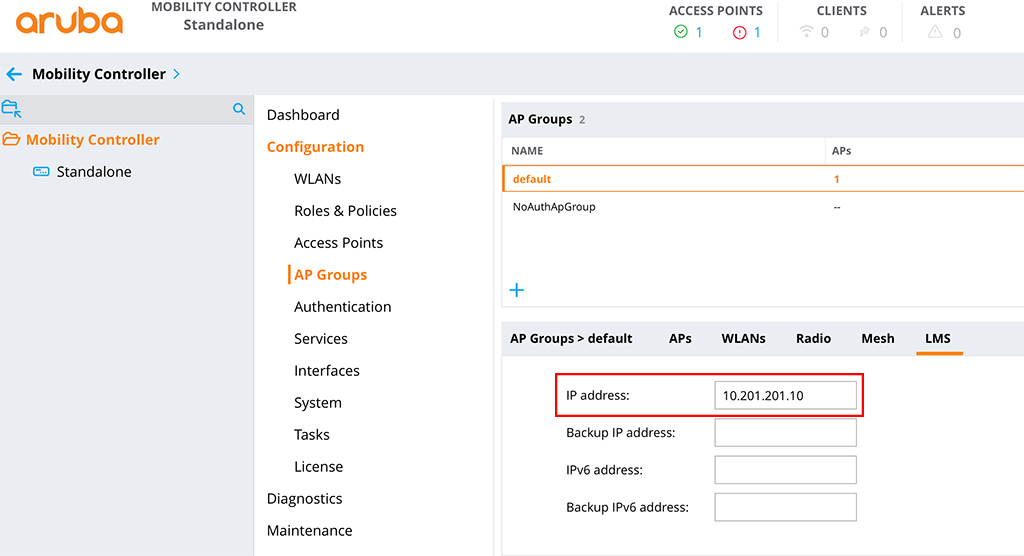
In the config it would look like this:
ap system-profile "default"
    session-acl ""
    lms-ip 10.201.201.10
    ap-console-password 6ff4d0d32c19eaf0cef1e5167b205a809127f17fb4638c1d
    bkup-passwords 114129e32c28546a0caabf2e7d391904913f992794a6508f
!
I use the default system profile for this test. The important option is the third line for the “
The next step is to configure the “GRE Striping IP”. The AP uses this IP for a secondary GRE tunnel to the controller. You do not need to configure this IP on an interface on the controller. Select this IP in a
To set the “GRE Striping IP” go to “Configuration–>System” and select the “Profiles” tab. Now select “AP” and “AP LACP LMS map information”:
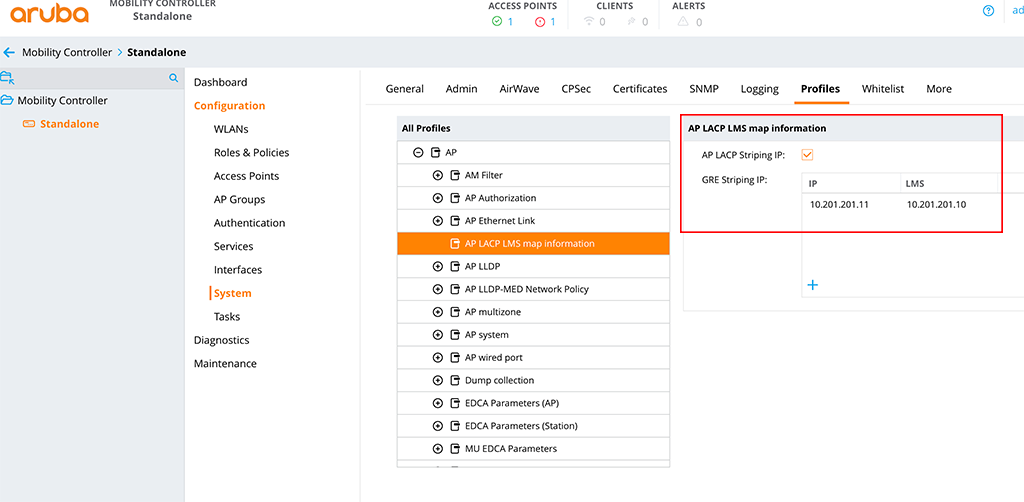
Enable “AP LACP Striping IP” and add the “GRE Striping IP” with the “LMS IP”. From the CLI it looks like this:
ap-lacp-striping-ip
    aplacp-enable
    striping-ip 10.201.201.11 lms 10.201.201.10
!(Standalone) [mynode] #show ap debug lacp ap-name a0:2b:b8:86:65:00 verbose
AP LACP GRE Striping IP: 10.201.201.11
AP LACP Status
--------------
Link Status LACP Rate Num Ports Actor Key Partner Key Partner MAC
----------- --------- --------- --------- ----------- -----------
Up slow 2 17 2 5c:8a:38:95:80:17
Slave Interface Status
----------------------
Slave I/f Name Permanent MAC Addr Link Status Member of LAG Link Fail Count
-------------- ------------------ ----------- ------------- ---------------
eth0 a0:2b:b8:86:65:00 Up Yes 0
eth1 a0:2b:b8:86:65:01 Up Yes 0
GRE Traffic Received on Enet Ports
----------------------------------
Radio Num Enet 0 Rx Count Enet 1 Rx Count
--------- --------------- ---------------
0 0 3980
1 136392 0
non-wifi 0 4819
Traffic Sent on Enet Ports
--------------------------
Radio Num Enet 0 Tx Count Enet 1 Tx Count
--------- --------------- ---------------
0 4478 0
1 0 48260
non-wifi 7159 45On the output above you find the “GRE Striping IP in the first line and in the lower part the load sharing between the two ethernet ports.
The “show ap database” command now includes the “s” flag for the AP’s with two ethernet interfaces:
(Standalone) [mynode] #show ap database

AP Database
-----------
Name               Group      AP Type  IP Address      Status         Flags  Switch IP       Standby IP
----               -----      -------  ----------      ------         -----  ---------       ----------
a0:2b:b8:86:65:00  default    225      10.200.200.100  Up 1h:34m:24s  2s     10.201.201.10   0.0.0.0
AP515              default    515      10.200.200.100  Down           2      10.201.201.10   0.0.0.0
RAP205             RAP-Group  205      10.0.0.24       Down           Rc2    10.201.201.111  0.0.0.0

Flags: 1 = 802.1x authenticated AP use EAP-PEAP; 1+ = 802.1x use EST; 1- = 802.1x use factory cert; 2 = Using IKE version 2
       B = Built-in AP; C = Cellular RAP; D = Dirty or no config
       E = Regulatory Domain Mismatch; F = AP failed 802.1x authentication
       G = No such group; I = Inactive; J = USB cert at AP; L = Unlicensed
       M = Mesh node
       N = Duplicate name; P = PPPoe AP; R = Remote AP; R- = Remote AP requires Auth;
       S = Standby-mode AP; U = Unprovisioned; X = Maintenance Mode
       Y = Mesh Recovery
       c = CERT-based RAP; e = Custom EST cert; f = No Spectrum FFT support
       i = Indoor; o = Outdoor; s = LACP striping; u = Custom-Cert RAP; z = Datazone AP
       p = In deep-sleep status

Total APs:3
Even with one Controller, the setup is very easy, even if it sounds complex in the first place.
LACP for AP’s with Instant AP’s
With Instant AP’s, it is very easy again. As they do not tunnel the traffic (except you use VPN for some SSID’s), all users are directly seen on the port. So it even does not matter, if you chose L2 or L3 load sharing on the switch. I have configured the switch as above for the CAP’s connected to a Controller cluster. Now, let’s check wh
AP LACP GRE Striping IP: 0.0.0.0


AP LACP Status
--------------
Link Status  LACP Rate  Num Ports  Actor Key  Partner Key  Partner MAC
-----------  ---------  ---------  ---------  -----------  -----------
Up           slow       2          17         2            5c:8a:38:95:80:17

Slave Interface Status
----------------------
Slave I/f Name  Permanent MAC Addr  Link Status  Member of LAG  Link Fail Count
--------------  ------------------  -----------  -------------  ---------------
eth0            a0:2b:b8:86:65:00   Up           Yes            0
eth1            a0:2b:b8:86:65:01   Up           Yes            0

Traffic Sent on Enet Ports
--------------------------
Radio Num  Enet 0 Tx Count  Enet 1 Tx Count
---------  ---------------  ---------------
0          0                0
1          0                0
non-wifi   2283             1045
You can see, that both links are up and part of a LAG. Unfortunately, on the IAP platform, you do not see the traffic distribution on both links. Here we need to check the switch:
[Aruba]dis interface GigabitEthernet 1/0/1
 GigabitEthernet1/0/1 current state: UP
 IP Packet Frame Type: PKTFMT_ETHNT_2, Hardware Address: 5c8a-3895-8019
 Description: GigabitEthernet1/0/1 Interface
 Loopback is not set
 Media type is twisted pair, Port hardware type is 1000_BASE_T
 1000Mbps-speed mode, full-duplex mode
 Link speed type is autonegotiation, link duplex type is autonegotiation
 Flow-control is not enabled
 The Maximum Frame Length is 9600
 Broadcast MAX-ratio: 100%
 Unicast MAX-ratio: 100%
 Multicast MAX-ratio: 100%
 PVID: 202
 Mdi type: auto
 Port link-type: trunk
  VLAN passing  : 1(default vlan), 200, 202, 204
  VLAN permitted: 1(default vlan), 2-4094
  Trunk port encapsulation: IEEE 802.1q
 Port priority: 0
 Last clearing of counters:  Never
 Peak value of input: 421 bytes/sec, at 2000-04-26 12:19:33
 Peak value of output: 380 bytes/sec, at 2000-04-26 12:17:48
 Last 300 seconds input:  2 packets/sec 421 bytes/sec 0%
 Last 300 seconds output:  1 packets/sec 314 bytes/sec 0%
 Input (total):  2016 packets, 238924 bytes
	 432 unicasts, 1308 broadcasts, 276 multicasts, 0 pauses
 Input (normal):  2016 packets, 238924 bytes
	 432 unicasts, 1308 broadcasts, 276 multicasts, 0 pauses
 Input:  0 input errors, 0 runts, - giants, - throttles
	 0 CRC, - frame, 0 overruns, 0 aborts
	 - ignored, - parity errors
 Output (total): 1074 packets, 194710 bytes
	 308 unicasts, 51 broadcasts, 715 multicasts, 0 pauses
 Output (normal): 1074 packets, 194710 bytes
	 308 unicasts, 51 broadcasts, 715 multicasts, 0 pauses
 Output: 0 output errors, - underruns, - buffer failures
	 0 aborts, 0 deferred, 0 collisions, - late collisions
	 - lost carrier, - no carrier

[Aruba]dis interface GigabitEthernet 1/0/3
 GigabitEthernet1/0/3 current state: UP
 IP Packet Frame Type: PKTFMT_ETHNT_2, Hardware Address: 5c8a-3895-801b
 Description: GigabitEthernet1/0/3 Interface
 Loopback is not set
 Media type is twisted pair, Port hardware type is 1000_BASE_T
 1000Mbps-speed mode, full-duplex mode
 Link speed type is autonegotiation, link duplex type is autonegotiation
 Flow-control is not enabled
 The Maximum Frame Length is 9600
 Broadcast MAX-ratio: 100%
 Unicast MAX-ratio: 100%
 Multicast MAX-ratio: 100%
 PVID: 202
 Mdi type: auto
 Port link-type: trunk
  VLAN passing  : 1(default vlan), 200, 202, 204
  VLAN permitted: 1(default vlan), 2-4094
  Trunk port encapsulation: IEEE 802.1q
 Port priority: 0
 Last clearing of counters:  Never
 Peak value of input: 4059 bytes/sec, at 2000-04-26 12:11:27
 Peak value of output: 861 bytes/sec, at 2000-04-26 12:18:33
 Last 300 seconds input:  2 packets/sec 724 bytes/sec 0%
 Last 300 seconds output:  2 packets/sec 701 bytes/sec 0%
 Input (total):  3127 packets, 1682001 bytes
	 2913 unicasts, 16 broadcasts, 198 multicasts, 0 pauses
 Input (normal):  3127 packets, 1682001 bytes
	 2913 unicasts, 16 broadcasts, 198 multicasts, 0 pauses
 Input:  0 input errors, 0 runts, - giants, - throttles
	 0 CRC, - frame, 0 overruns, 0 aborts
	 - ignored, - parity errors
 Output (total): 2681 packets, 571917 bytes
	 2513 unicasts, 42 broadcasts, 126 multicasts, 0 pauses
 Output (normal): 2681 packets, 571917 bytes
	 2513 unicasts, 42 broadcasts, 126 multicasts, 0 pauses
 Output: 0 output errors, - underruns, - buffer failures
	 0 aborts, 0 deferred, 0 collisions, - late collisions
	 - lost carrier, - no carrier
You can see in and out packets on both interfaces, so we know, that LACP and traffic distribution is working.
This concludes this post. Did you use redundant connected AP’s in you environment?
If you find this post useful, leave me a comment and share it with your friends. If you don’t like the post, leave me a comment and tell me what you don’t like. But whatever you do, leave me a comment.
Another great hands-on blog, thanks. Keep them coming, please 🙂
Thanks for the feedback. Really appreciated. I currently write the next one 🙂
Just came across your blog, a lot of really useful information, thanks!
What happens if the AP is connected on both ethernet ports without LACP? Will they operate active/passive with a bootstrap during link failover? Or will it create a looping scenario?
Hi,
If you connect the AP to both ports without LACP enabled on the switch, the AP will go into active/passive. If the AP needs to bootstrap after a link failure depends of the AP, if it is an older 2xx/3xx AP it will bootstrap, if it is a 34x/5xx AP it will just work with the other port.
I assume, that the AP is either powered with an external Power source or both ports deliver PoE. Both will work.
BR
Florian
Hi florian,
Great guide as usual.
I tried the configuration and the verification commands are all good.
However I am experiencing huge amount of packet loss when the LM stripping is enabled.
The moment is disable it goes back to normal.
AP is 515, upstream switch is 2930F . TRK is configured in LACP mode.
Hi,
which version are you running and do you use a cluster setup?
BR
Florian
Hi,
Good Day. I would like to confirm if the dual Port in the AP can be used as active/standby setup.
If it’s possible to deploy such way with Aruba and whether its a recommend approach. In our environment we are trying to deploy 555 model AP, but seeing with two MAC address being learnt on Eth 1 interface, which is causing issues with authentication setup in our environment
Hi Parthi,
The normal behavior of our AP’s with two ethernet interfaces is to use them in an active/passive approach (from a data point of view). If you would like to use both ports for active/active I would enable LACP for those ports on the switch. My recommendation would be to use LACP instead of active/passive.
Do you use CAP or IAP’s?
BR
Florian
Thanks for your easy to follow guide. I have LACP working on some test APs with etherChannel configured on my cisco switch, and in my Aruba cluster environment (2 controllers). Using the “show ap debug lacp ap-name” command I do see that my UAC traffic is split between the two ethernet ports of the AP. And I can see under the “GRE Traffic SENT on Enet Ports” section that the traffic does seem split between the two. However, under the “GRE Traffic RECEIVED on Enet Ports” section, it appears the GRE traffic is coming into the AP on only one of the ports. The cisco switch load balance config is set for “src-ip” which I thought would work since the two controllers have two different IPs. Any thoughts on how to get the inbound GRE traffic spread over both ports?
Hi CodyE,
That’s interesting. From my point of view, the traffic should be split between the two uplinks. But for this specific issue, you should try to work with your switch vendor. Looks like it is a Cisco switch (because of EtherChannel) so I would try to ask the question in their community or discuss this with your peers within cisco.
BR
Florian
I am enjoying your blog.
What should I do when two controllers in standalone mode are redundant and configured as HA?
Hi,
To my understanding, this should work the same. you would need to add two GRE Striping IP’s pairs, one for the active controller and one for the backup controller.
BR
Florian
Hi, great post!
I have a question regarding active/standby as I want to use nac on the ports (basic mab) however this mode is not working with nac as e0 Mac is also seen on e1 port after authentication and the switch de-auth the port.
Do you have any recommendations on how to use nac along with dual ports for redundancy?
Hi JS,
This is not possible. You cannot authenticate on switch ports that are bound to a trunk (link aggregation). At least with the switches, I know. But you should ask your switch vendor if this is possible.
BR
Florian
Hello,
Thanks for proving this information,
We have 1 mobility master with 2 controller and around 158 AP. We are going to install new AP535 for our big Salon and use both ports for each AP. For the moment I have configured LACP in HUAWEI(5700) sw and in mobility master for my specific AP group add LMS with 2 IP(one for backup). Do I need to do any thing else or not?
In Airwave we see that Port eth1 in Active/Standby mode and the second one in N/A mode.
Could you please let me know if we are in good way ro we need to reconfig something in MM or in SW ?
Thanks a lot,
Best
Ghasem
Hi Ghasem,
Are you running the two controllers in a cluster?
What is the command “show ap debug lacp ap-name name-of-ap verbose” shows you?
BR
Florian
Hi Florian,
Thanks for your message. Yes, we run two controller in our cluster.
(MC1) [MDC] #show ap debug lacp ap-name ap-535-test verbose
LACP Not Configured
Any Idea?
BR
Ghasem
Hi,
Please find below the output command of show ap debug lacp ap-name ap-535-test verbose:
(MC1) [MDC] #show ap debug lacp ap-name ap-535-test verbose
AP LACP GRE Striping IP: 0.0.0.0
AP LACP Status
————–
Link Status LACP Rate Num Ports Actor Key Partner Key Partner MAC
———– ——— ——— ——— ———– ———–
Up slow 2 11 321 6c:34:91:42:61:61
Slave Interface Status
———————-
Slave I/f Name Permanent MAC Addr Link Status Member of LAG Link Fail Count
————– —————— ———– ————- —————
eth0 f0:61:c0:cb:6c:2a Up Yes 0
eth1 f0:61:c0:cb:6c:2b Up Yes 0
GRE Traffic Received on Enet Ports
———————————-
Zone Index Controller IP Enet 0 Rx Count Enet 1 Rx Count
—- —– ————- ————— —————
0 0 192.168.x.y 0 0
0 1 192.168.x.y1 0 0
GRE Traffic Sent on Enet Ports
——————————
Zone Index Controller IP Enet 0 Tx Count Enet 1 Tx Count
—- —– ————- ————— —————
0 0 192.168.x.y 0 0
0 1 192.168.x.y1 0 0
Link Aggregation UACs outgoing interface
———————————
zone=0 idx=0 IPv4=192.168.x.y odev=eth0
zone=0 idx=1 IPv4=192.168.x.y1 odev=eth1
———————————
eth0 UACs 1
eth1 UACs 1
(MC1) [MDC] #
Thanks again,
Hi,
Please find the output command below:
(MC1) [MDC] #show ap debug lacp ap-name ap-535-test verbose
AP LACP GRE Striping IP: 0.0.0.0
AP LACP Status
————–
Link Status LACP Rate Num Ports Actor Key Partner Key Partner MAC
———– ——— ——— ——— ———– ———–
Up slow 2 11 321 6c:34:91:42:61:61
Slave Interface Status
———————-
Slave I/f Name Permanent MAC Addr Link Status Member of LAG Link Fail Count
————– —————— ———– ————- —————
eth0 f0:61:c0:cb:6c:2a Up Yes 0
eth1 f0:61:c0:cb:6c:2b Up Yes 0
GRE Traffic Received on Enet Ports
———————————-
Zone Index Controller IP Enet 0 Rx Count Enet 1 Rx Count
—- —– ————- ————— —————
0 0 192.168.x.y 0 0
0 1 192.168.x.y1 0 0
GRE Traffic Sent on Enet Ports
——————————
Zone Index Controller IP Enet 0 Tx Count Enet 1 Tx Count
—- —– ————- ————— —————
0 0 192.168.x.y 0 0
0 1 192.168.x.y1 0 0
Link Aggregation UACs outgoing interface
———————————
zone=0 idx=0 IPv4=192.168.x.y odev=eth0
zone=0 idx=1 IPv4=192.168.x.y1 odev=eth1
———————————
eth0 UACs 1
eth1 UACs 1
Hi,
Please find the output command in below:
(MC1) [MDC] #show ap debug lacp ap-name ap-535-test verbose
AP LACP GRE Striping IP: 0.0.0.0
AP LACP Status
————–
Link Status LACP Rate Num Ports Actor Key Partner Key Partner MAC
———– ——— ——— ——— ———– ———–
Up slow 2 11 321 6c:34:91:42:61:61
Slave Interface Status
———————-
Slave I/f Name Permanent MAC Addr Link Status Member of LAG Link Fail Count
————– —————— ———– ————- —————
eth0 f0:61:c0:cb:6c:2a Up Yes 0
eth1 f0:61:c0:cb:6c:2b Up Yes 0
GRE Traffic Received on Enet Ports
———————————-
Zone Index Controller IP Enet 0 Rx Count Enet 1 Rx Count
—- —– ————- ————— —————
0 0 192.168.x.y 0 0
0 1 192.168.x.y1 0 0
GRE Traffic Sent on Enet Ports
——————————
Zone Index Controller IP Enet 0 Tx Count Enet 1 Tx Count
—- —– ————- ————— —————
0 0 192.168.x.y 0 0
0 1 192.168.x.y1 0 0
Link Aggregation UACs outgoing interface
———————————
zone=0 idx=0 IPv4=192.168.x.y odev=eth0
zone=0 idx=1 IPv4=192.168.x.y1 odev=eth1
———————————
eth0 UACs 1
eth1 UACs 1
(MC1) [MDC] #
Thank you
BR
Ghasem
Hi Ghasem,
with a cluster setup, you do not need to do anything special on the AP’s, just make sure, that the switch is configured to send LACP BPDU’s. When the AP’s boots it will receive the LACP BPDU’s on both ports and will enable LACP as well, to form a link aggregation. From the outbove above I can see, that you are already sucessfull with your setup 🙂
You might check on the interface stats of the switch, to proof, that traffic is going through both ports.
BR
Florian
Hi,
Thank for your comment,
I can confirm that both sw and controller playing their role well.
Thanks again for your time and excellent post. Good luck
Its helpful
BR
Ghasem
Hi Ghasem,
glad to hear that it is now working for you.
Thanks for your feedback. Much appreciated.
BR
Florian
Hello,
First I would like to tell you I do not find any way to contact with you, then I have to put my question here:
I find issue “PTK Challenge Failed” issue in random clients which always complain we lost our connection.
We have MM with running version 8.10.0.6 LSR with 2 controller (Model7502) and 158 APs with same image version.
I would like to get rid of this issue, Could you please share with me your experience in this regards?
is disabling OKC and Prohibit IP spoofing can help ?
I used these commands but still did not find answer:
show ap client trail-info
show ap debug radio-stats ap-name xxxx radio 0 advanced
show auth-tracebuf mac
show ap debug client-table ap-name xxxx
show ap debug client-deauth-reason-counters
(MC1) [MDC] *#show ap debug client-deauth-reason-counters
Deauth Reason Counters
———————-
Name Value
—- —–
Denied; Ageout 8
Unspecified Failure 451895
No STA 36
Prior authentication is not valid 909
UAC Changed 74
STA has left and is deauthenticated 10474
Inactive Timer expired and STA was disassociated 1196
Class 2 frames from non authenticated STA 42
C-STM deauthed STA; AID mismatch 18
Class 3 frames from non associated STA 109
STA has left and is disassociated 58550
STA has roamed to another AP 912463
Auth STA up failed 69
Station Up Message to Controller Timed Out 15
Requested authentication algorithm not supported 23991
Response to challenge failed 15716
APAE Disconnect 4090
Response to EAP Challenge Failed 12864
Key Propagation Failed 840
Wlan driver wireless client out of range 30024
Client Match 578
Ptk Challenge Failed 3276870
Sapcp Ageout (internal ageout) 9847
Denied; AP Going Down 406
MC2
(MC2) [MDC] *#show ap debug client-deauth-reason-counters
Deauth Reason Counters
———————-
Name Value
—- —–
Denied; Ageout 16
Unspecified Failure 292038
Prior authentication is not valid 80
No STA 36
UAC Changed 77
STA has left and is deauthenticated 13220
Inactive Timer expired and STA was disassociated 1272
Class 2 frames from non authenticated STA 24
C-STM deauthed STA; AID mismatch 28
Class 3 frames from non associated STA 72
STA has left and is disassociated 71600
STA has roamed to another AP 895613
Auth STA up failed 205
Station Up Message to Controller Timed Out 14
Requested authentication algorithm not supported 24817
Response to challenge failed 13195
APAE Disconnect 11174
Response to EAP Challenge Failed 35616
Key Propagation Failed 866
Wlan driver wireless client out of range 37470
Client Match 621
Ptk Challenge Failed 2960195
Sapcp Ageout (internal ageout) 9830
Denied; AP Going Down 477
(MC2) [MDC] *#
Any Hint?
Thank you so much
Gh
Hi Ghasem,
Thanks for your comment. The best way to get in touch with me is either the comment function, which you chose, or writing an email, which can be found in all of the legal pages, like imprint…
My first advice would be to update to the latest version of 8.10, which is 8.10.0.12. If the issue still exists I would create a case with Aruba and provide all the required information, like client type, AP type, tech logs, physical environment. They should be able to help.
BR
Florian