This post is about the IRF MAD detection methods, used
With IRF MAD we have four technic’s to prevent this. They are:
- LACP MAD
- BFD MAD
- ARP MAD
- ND MAD
This post will not describe any configuration details of each technic, but will explain how they work and what the difference is, between Comware5 and Comware7.
IRF MAD Detection
The purpose of IRF MAD detection is to detect, if the IRF cluster is working properly, by comparing the IRF domain ID and the IRF active ID of every IRF member. The IRF active ID is the ID of the master. For a healthy IRF cluster those ID’s should be the same for every IRF member. If a split of the IRF cluster occur, IRF MAD detects this split, as the IRF active ID will be different for some members of the IRF cluster.
Now, IRF MAD needs to handle this collision and decide which part of the IRF cluster should stay online and which part should shut down, to prevent the split-brain scenario. IRF MAD uses the IRF member ID to decide which part if the cluster should stay in the active state. The IRF master with the lowest member ID wins and all IRF members, connected to that master will stay in the active state. All other devices in the IRF cluster will enter the recovery state and shuts down all ports, except the ones, which where excluded with the “mad exclude interface” command and the IRF ports.
After repairing the failed IRF link or the failed device, you can merge the IRF cluster again. This will include an IRF merge of the IRF fabric which is in the active state with the one, which is in the recovery state.
You can achieve the split-brain protection, provided by IRF MAD and described above by using one of the mentioned IRF MAD detection technic’s. I will explain how they work in the next sections.
LACP MAD
LACP MAD is working with extended TLV’s of the LACP protocol. Every IRF member
Lets assume, you have an IRF cluster as below:
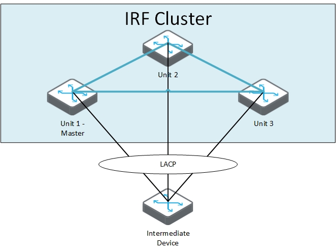
Within this scenario, the LACP packets from each IRF member contain the information of the IRF domain and the IRF active (master) ID. The intermediate device forwards the Packets on every link in the bridge aggregation and every IRF member can compare the information with its own information. If the link between Unit 1 and Unit 2 and Unit 3 failed, like in the picture below, the situation is completely changed:
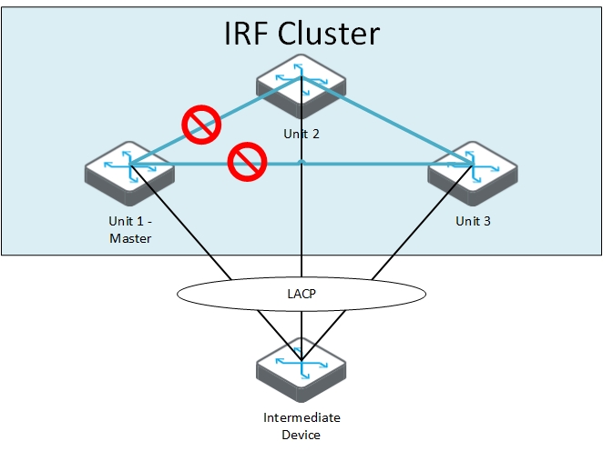
The content of the LACP packages will change now, as Unit 1 is the master for itself and either Unit 2 or Unit 3 is the master for the rest of the IRF cluster. The devices, receiving those information know, that an IRF failure has occurred and they need to follow the MAD algorithm to prevent network outages. Therefore they compare the active ID with the information they have. The part of the IRF cluster with a higher active ID will enter the recovery state. In our example, Unit 1 has the lowest active ID. This would mean, that Unit 2 and 3 are entering recovery state and disable all ports except the IRF ports, the console port and the ports excluded by IRF MAD.
We now have the situation, that two of three switches are down and cannot serve your clients. Starting with comware7, HP changed the algorithm slightly. With comware7 (and only with comware7 and LACP MAD) the number of connected devices is taken into account too.
Going back to the scenario above, the three switches discover through IRF MAD that there is a split brain and the two IRF masters are online. Before comparing the active ID, they would compare the number of members in each new cluster. The cluster with the highest number wins. In our scenario above, Units 2 and 3 will stay online and Unit 1 will enter the recovery state, even when the active id is lower. This will lead to a situation, with two of three switches online. Which is better than before. If two or more parts of the IRF cluster have the same amount of members, the active ID will be used to detect, which has the lowest one.
This is only working with comware7 and LACP MAD. If you are working with comware7 switches, please do not mix this detection method with others, as all others working with the algorithm from comware5. This can create unpredictable situations.
BFD MAD
BFD MAD is using a dedicated link between each member of the IRF cluster. To save ports, you can also use an intermediate device. You also have to create a dedicated VLAN for IRF MAD on each device and each device would need a dedicated IP for that VLAN. When everything is working fine, the master is trying to reach all IRF members, using that link. As all members will shut down the IRF MAD ports during normal operations, the connection attempt will fail. This will show the master, that he is the one and only
If there is a split brain happening, another master will be elected and this master will enable the BFD MAD port. The two masters can now use the BFD link to exchange IRF domain and active ID and decide which part of the cluster has to enter recovery state. From this point, the process works the same as for LACP MAD with comware5. Currently, it is not supported to exchange information of the amount of members with BFD MAD.
ARP MAD
ARP MAD will use ARP packets for the exchange of the IRF domain and active ID. During normal operations, those information’s should be the same for every member of the IRF cluster. If a split brain occur, the IRF active ID will change for some members in the IRF cluster and the normal decision process starts. Lowest active ID wins. All other have to enter recovery state.
ND MAD
ND MAD uses the ND’s protocol’s NS packages to exchange the information for IRF domain and active ID. The process is the same as for ARP MAD and will produce the same outcome.
Conclusion
When working with comware5 devices, you can chose between those methods and combine them as needed, to get even higher protection against split brain scenarios. If you are working with comware7 switches, you need to decide of you would like to use LACP MAD or a combination of the other methods. Don’t mix LACP MAD on comware7 with the other methods. You cannot determine what will happen in a failure scenario, as you cannot know, which method is detecting the split first.
There is one exception to this rule, as always. If you only have two switches in an IRF cluster, it doesn’t matter which method is used, as the outcome is always the same.
Sources
There is an excellent article about IRF MAD on aboutnetworking.com:
I also used the information from the IRF manual from 5900:
and the IRF manual from the 5800:
Thanks for reading this post. If you have questions, or want to send me feedback, you can use the comment function below.