This post will describe one option to implement a VXLAN enabled fabric. I will use VSR router to create the fabric and create the overlay using VXLAN.
I already gave a general overview about VXLAN in an earlier post here:
VXLAN: What is VXLAN
VXLAN Implementation Introduction
Before I will start to describe the configuration I would like to present the lab environment, which was used to create the setup.Everything was tested within a virtual environment. This means, I created the setup, using an ESXi server. On this server, I have created the following topology, using VSR router, to create the test environment:
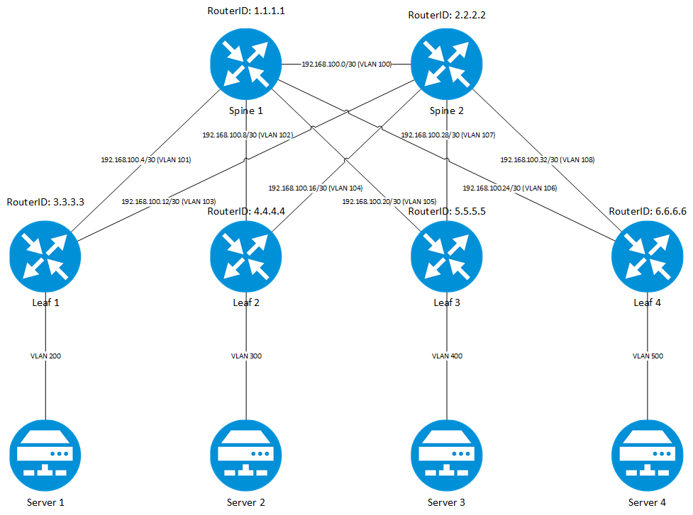
I have created a typical CLOS fabric using the Virtual Service Router VSR and using OSPF to create the layer 3 fabric. I have also attached 4 Linux servers based on Debian. They are purely configured as clients and they are not VXLAN aware.Every connection is a separate VLAN on the ESXi virtual switch, to make sure, that each connection can operate independently of any other without direct interaction. Every connection in the fabric is a p-2-p connection, using routed interfaces on both ends.
VXLAN Implementation
The configuration of VXLAN is quite simple and needs only a few lines in the configuration. I will use as much automation as possible. I will use IS-IS to learn mac addresses in the fabric and I will use ENDP (Enhanced Neighbor Discovery Protocol) to share the information about VTEP’s and to create the tunnels. Let’s start from the beginning and show the configuration of Leaf 1. Both Spine devices are not VXLAN aware and simply forward the UDP packets, created by the Leaf devices. The first step is to create a VSI (Virtual Switching Instance) which is a virtual switch, running on the device to hold all information, which is needed to switch the packets within the VXLAN. To create the VSI, I need to enable the layer 2 VPN feature on the device:
l2vpn enableAfter the layer 2 VPN feature is enabled, I need to create the virtual switching instance:
vsi site-1
description vsi-site-1
arp suppression enable
vxlan 1
There many options for the VSI, which can be configured. I will only use three of them. The description, to insert more information for other admins, which maybe need to work and configure the device.
The most important option is the VXLAN option, which defines for which VXLAN the VSI is used. Every VXLAN needs one VSI.
The “arp suppression enable” one, will allow the VTEP to answer local ARP requests for remote devices, to reduce the amount of traffic in the VXLAN tunnel.
The next step is to create the VXLAN tunnel, which is used to send the encapsulated packets over the fabric. Different VXLAN networks can use the same VXLAN tunnel.
This tunnel can be created manually between VTEP’s, which is good for environments with a small number of VTEP’s or environments which are very static. For environments with more VTEP’s or which grow dynamically, an automatic mechanism is available to create the tunnels between different VTEP’s, My suggestion is to use the automatic mechanism to create the tunnels as this will make future changes much easier.
The manual way is described in the manual, which is linked at the end of the post.
The automatic procedure is using the Enhanced Neighbor Discovery Protocol (ENDP). ENDP is used to discover all available VTEP’s in a network. Share the information among those VTEP’s about other VTEP’s to make sure that they establish a VXLAN tunnel among them and build a full mesh, between all VTEP’s.
The
The ENDC (Enhanced Neighbor Discovery Client) is a VTEP’s which connects to the ENDS to announce himself to ENDS and to get the information about other ENDC’s in the network, to create VXLAN tunnels to those
The ENDS can be a VTEP or another device, not involved in the VXLAN stuff. In my setup, I use one of the Spine devices to be the ENDS.
To configure the ENDS the following configuration is required:
interface Tunnel0 mode nve
 source 1.1.1.1
 network-id 1
 vxlan neighbor-discovery server enable
The source interface, used in this example is a previously created loopback interface and is distributed in the fabric using OSPF.
The network-id is used to
The last command (line 4) enabled the server and makes the server accessible for the clients.
To configure the client, the following steps are required:
interface Tunnel0 mode nve
 source 3.3.3.3
 network-id 1
 vxlan neighbor-discovery client enable 1.1.1.1
It looks the same as the server configuration. The only difference is the last line. Here, the client is enabled and the server address is configured.
If everything is working correctly the server should list all
<Spine1>display vxlan neighbor-discovery server summary
Interface      Local Address   Network ID    Auth        Members    VPN Instance
Tunnel0        1.1.1.1         1             disabled    5          [No Vrf]
This command will show the used tunnel interface and the number of attached clients.
<Spine1> display vxlan neighbor-discovery server member
Interface: Tunnel0    Network ID: 1    Vpn-instance: [No Vrf]
IP Address: 1.1.1.1
Client Address  System ID         Expire    Created Time
1.1.1.1         cc3e-5f81-9bff    61        2016/07/22 21:06:29
3.3.3.3         cc3e-5f82-0f83    71        2016/07/22 21:06:39
4.4.4.4         cc3e-5f81-a565    67        2016/07/22 21:06:35
5.5.5.5         cc3e-5f81-cabf    68        2016/07/22 21:06:36
6.6.6.6         cc3e-5f81-927a    72        2016/07/22 21:06:40
The show command above will list the connected clients. Make sure, you see all VTEP’s, which are running ENDP as clients.
<Spine1>display vxlan neighbor-discovery client member
Interface: Tunnel0    Network ID: 1    Vpn-instance: [No Vrf]
Local Address: 1.1.1.1
Server Address: 1.1.1.1
Neighbor        System ID         Created Time           Expire    Status
3.3.3.3         cc3e-5f82-0f83    2016/07/22 21:06:44    64        Up
4.4.4.4         cc3e-5f81-a565    2016/07/22 21:06:44    64        Up
5.5.5.5         cc3e-5f81-cabf    2016/07/22 21:06:44    64        Up
6.6.6.6         cc3e-5f81-927a    2016/07/22 21:06:44    64        Up
To get the information if all clients are up and running, you can use the display command above.
As all VTEP’s are now aware of all the other VTEP’s, they should have established VXLAN tunnel among each other. On a VTEP, I will very this, using this command:
<Spine1>display interface tunnel
Tunnel1
Current state: UP
Line protocol state: UP
Description: Tunnel1 Interface
Bandwidth: 64kbps
Maximum Transmit Unit: 64000
Internet protocol processing: disabled
Output queue - Urgent queuing: Size/Length/Discards 0/100/0
Output queue - Protocol queuing: Size/Length/Discards 0/500/0
Output queue - FIFO queuing: Size/Length/Discards 0/75/0
Last clearing of counters: Never
Tunnel source 3.3.3.3, destination 1.1.1.1
Tunnel protocol/transport UDP_VXLAN/IP
Last 300 seconds input rate: 0 bytes/sec, 0 bits/sec, 0 packets/sec
Last 300 seconds output rate: 21 bytes/sec, 168 bits/sec, 0 packets/sec
Input: 0 packets, 0 bytes, 0 drops
Output: 19950 packets, 1256850 bytes, 0 drops

Tunnel2
Current state: UP
Line protocol state: UP
Description: Tunnel2 Interface
Bandwidth: 64kbps
Maximum Transmit Unit: 64000
Internet protocol processing: disabled
Output queue - Urgent queuing: Size/Length/Discards 0/100/0
Output queue - Protocol queuing: Size/Length/Discards 0/500/0
Output queue - FIFO queuing: Size/Length/Discards 0/75/0
Last clearing of counters: Never
Tunnel source 3.3.3.3, destination 4.4.4.4
Tunnel protocol/transport UDP_VXLAN/IP
Last 300 seconds input rate: 8 bytes/sec, 64 bits/sec, 0 packets/sec
Last 300 seconds output rate: 36 bytes/sec, 288 bits/sec, 0 packets/sec
Input: 6956 packets, 500589 bytes, 0 drops
Output: 26953 packets, 2153275 bytes, 0 drops

Tunnel3
Current state: UP
Line protocol state: UP
Description: Tunnel3 Interface
Bandwidth: 64kbps
Maximum Transmit Unit: 64000
Internet protocol processing: disabled
Output queue - Urgent queuing: Size/Length/Discards 0/100/0
Output queue - Protocol queuing: Size/Length/Discards 0/500/0
Output queue - FIFO queuing: Size/Length/Discards 0/75/0
Last clearing of counters: Never
Tunnel source 3.3.3.3, destination 5.5.5.5
Tunnel protocol/transport UDP_VXLAN/IP
Last 300 seconds input rate: 8 bytes/sec, 64 bits/sec, 0 packets/sec
Last 300 seconds output rate: 36 bytes/sec, 288 bits/sec, 0 packets/sec
Input: 7013 packets, 507901 bytes, 0 drops
Output: 32132 packets, 2470006 bytes, 0 drops

Tunnel4
Current state: UP
Line protocol state: UP
Description: Tunnel4 Interface
Bandwidth: 64kbps
Maximum Transmit Unit: 64000
Internet protocol processing: disabled
Output queue - Urgent queuing: Size/Length/Discards 0/100/0
Output queue - Protocol queuing: Size/Length/Discards 0/500/0
Output queue - FIFO queuing: Size/Length/Discards 0/75/0
Last clearing of counters: Never
Tunnel source 3.3.3.3, destination 6.6.6.6
Tunnel protocol/transport UDP_VXLAN/IP
Last 300 seconds input rate: 8 bytes/sec, 64 bits/sec, 0 packets/sec
Last 300 seconds output rate: 36 bytes/sec, 288 bits/sec, 0 packets/sec
Input: 6954 packets, 500441 bytes, 0 drops
Output: 26969 packets, 2154557 bytes, 0 drops
The above command will list all create tunnels and the detailed information for those tunnels. Leaf 1 has established tunnels with all other VTEP’s (Tunnel2, Tunnel3 and Tunnel4) and they are all up and running.
If a new VTEP is added and ENDP is enabled on this VTEP, the existing VTEP’s will create a tunnel to the new one as well.
The next
This could be done manually, but I prefer to do this automatically. To assign VXLAN networks to VXLAN tunnels IS-IS is used. With IS-IS, the VTEP’s will exchange information about available VXLAN networks and if two VTEP’s have the same VXLAN network configured, they will put this one automatically on the VXLAN tunnel between them. This makes it easy, as I only have to create the VXLAN networks on the VTEP’s, without the need to configure all tunnels.
The first step is to reserve one VXLAN
reserved vxlan 1000The last step is to enable IS-IS:
vxlan-isis
 negotiate-vni enable
 mac-synchronization enable
The second line, will enable IS-IS and allow the exchange about VXLAN networks. The third line is already the first optimization step. This will make sure, that learned local MAC addresses are distributed in the network, using IS-IS. This should reduce the amount of broadcast in the network, together with the previously mentioned arp suppression feature.
To assign real traffic to the VXLAN network, I need to tell the device, from which port, the incoming traffic should be assigned to the VXLAN:
interface GigabitEthernet3/0
 port link-mode route
 xconnect vsi site-1
I s
To check if everything is working correctly I will use the following display commands:
[Leaf1]display l2vpn vsi verbose
VSI Name: site-1
  VSI Index               : 0
  VSI Description         : Server1/3
  VSI State               : Up
  MTU                     : 1500
  Bandwidth               : -
  Broadcast Restrain      : -
  Multicast Restrain      : -
  Unknown Unicast Restrain: -
  MAC Learning            : Enabled
  MAC Table Limit         : -
  MAC Learning rate       : -
  Drop Unknown            : -
  Flooding                : Enabled
  Statistics              : Disabled
  VXLAN ID                : 1
  Tunnels:
    Tunnel Name          Link ID    State  Type
    Tunnel3              0x5000003  Up     Auto
  ACs:
    AC                               Link ID    State
    GE3/0                            0          Up
The command above will list all VSI’s and the assigned tunnels. The VSI “site-1” is only configured on Leaf 1 and Leaf 3. The tunnel between those two VTEP’s is Tunnel3. The VXLAN id for this VXLAN network is 1. Everything looks correct on this one.
Let’s check if
[Leaf1] display l2vpn mac-address
MAC Address      State    VSI Name                        Link ID/Name  Aging
000c-296f-b384   Dynamic  site-1                          0             Aging
--- 1 mac address(es) found  ---
As Leaf 1 is now aware of the MAC address of Server 1, this MAC address is distributed to Leaf 3 by IS-IS:
[Leaf1] display l2vpn mac-address
MAC Address      State    VSI Name                        Link ID/Name  Aging
000c-296f-b384   IS-IS    site-1                          Tunnel2       NotAging
--- 1 mac address(es) found  ---
The difference from Leaf 1 is, that the State is IS-IS and that there is a Tunnel assigned to the MAC, which is Tunnel2, as on Leaf 3, the tunnel to Leaf 1 is Tunnel2. If Server 3, which is connected to Leaf 3 is trying to reach Server 1, no broadcast is needed as the MAC address is already known to the VTEP and the VTEP will answer the ARP request, instead of broadcasting the request through the VXLAN tunnels.
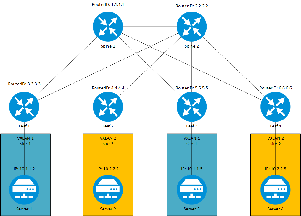
At the end, I have created the following VXLAN assignments:
VXLAN Documentation: Those are the essential steps, to create a VXLAN environment. Of curse, there are many more options to tweak and enhance the functionality.
VXLAN Manual for the VSR Router
VXLAN Manual for the 5930 Switches
VXLAN Manual for the 5950 Switches
VXLAN Manual for the 7500 Switches
VXLAN Manual for the 7900 Switches
VXLAN Manual for the 10500 Switches
VXLAN Manual for the 12900 Switches
If you have any questions please use the comment function below. If you would like to provide feedback please contact me or use the comment function as well.
When you come to Brazil, I’ll buy you a round of beer and pizza, lol.
Hi Rafael,
When I visit Brrazil in the future I will hunt you down for the round of beer 🙂
BR
Florian