In Mai, I was on a proof of concept in Grenoble and one of the coolest things was the Private VLAN function in Comware 7. It was really interesting to see how it works and how simple it is to separate hosts from each other.
It works with a two-tier approach. There is a primary VLAN, which is used for L3 forwarding and interconnecting the secondary VLAN’s with each other when needed.
The secondary VLAN’s are used to put the clients in. Secondary VLAN’s are isolated on L2 from each other. It is configurable if clients in the same secondary VLAN’s can communicate with each other.
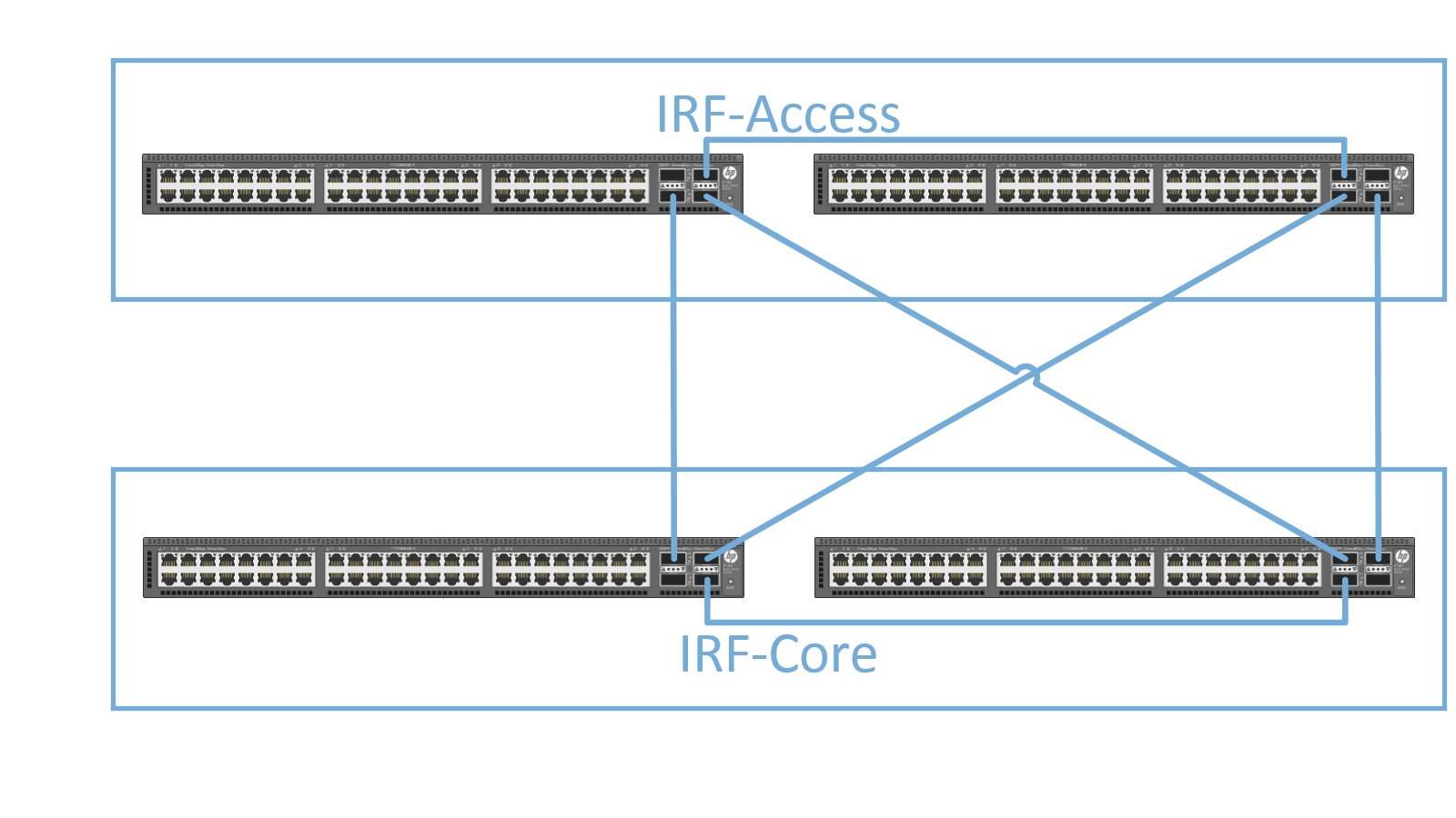
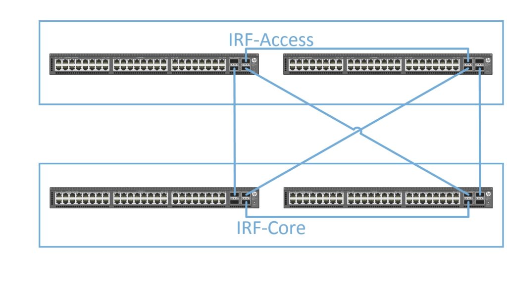
To test this feature, we used the 5900’s as access devices and core devices in the topology below:
We will create some secondary access VLAN’s on the IRF-Access devices.
VLAN 11
VLAN 12
VLAN 13
VLAN 14
The primary VLAN is VLAN 10, which needs also be configured:
vlan 10
   private-vlan primary
   private-vlan secondary 11 to 14

vlan 11
   private-vlan isolated

vlan 12
   private-vlan isolated

vlan 13

vlan 14
The “private-
You do not have to make any special configurations for the secondary VLAN’s, except clients in the same secondary VLAN are not allowed to communicate with each other. Then you have to issue this statement in the VLAN
To configure the secondary VLAN’s on the access ports just issue those two commands on the access port:
port access vlan 11
port private-vlan host
Afterward, the port configuration should look like this:
#interface Ten-GigabitEthernet1/0/1
   port link-mode bridge
   port link-type hybrid
   undo port hybrid vlan 1
   port hybrid vlan 10 to 11 untagged
   port hybrid pvid vlan 11
   port private-vlan host
   link-delay 0
#
Do this also for all the other ports. Next step is to configure the uplink port. Configure the port as a trunk port and permit the primary VLAN’s with this command.
port private-vlan 10 trunk promiscuousThe port configuration should look like this:
#interface Bridge-Aggregation10
   description LINK TO DC1-CORE
   port link-type trunk
   undo port trunk permit vlan 1
   port trunk permit vlan 10 to 14
   port private-vlan 10 trunk promiscuous
   link-aggregation mode dynamic
#
On the IRF-Core we just need to configure VLAN 10 as a normal VLAN with a VLAN interface and IP address, which will be the gateway for all clients in the secondary VLAN’s and offer L3 connectivity. Clients in VLAN 11 and 12 are not allowed to communicate with each other and with clients in VLAN 13 and 14. Clients in VLAN 13 and 14 are allowed to communicate with other clients within the same VLAN but not with Clients in other secondary VLAN’s. To allow inter VLAN communication between secondary VLAN’s you have to issue the following command on the VLAN 10 interface on IRF-Core:
local-proxy-arp enableThis will allow communication between secondary VLAN’s. As you can see, the configuration is very simple and handy.